Advanced Topics#
External clock issues for OCT applications#
The external clocking feature of AlazarTech boards is commonly used in Optical Coherence Tomography (OCT) applications, where swept laser sources generate a signal to be used for clocking the acquisition. However, in some cases the external clock signal does not meet the requirements of the digitizers, which can lead to various issues. This section discusses the steps that need to be taken to diagnose and troubleshoot external clock problems.
Diagnose external clock issues#
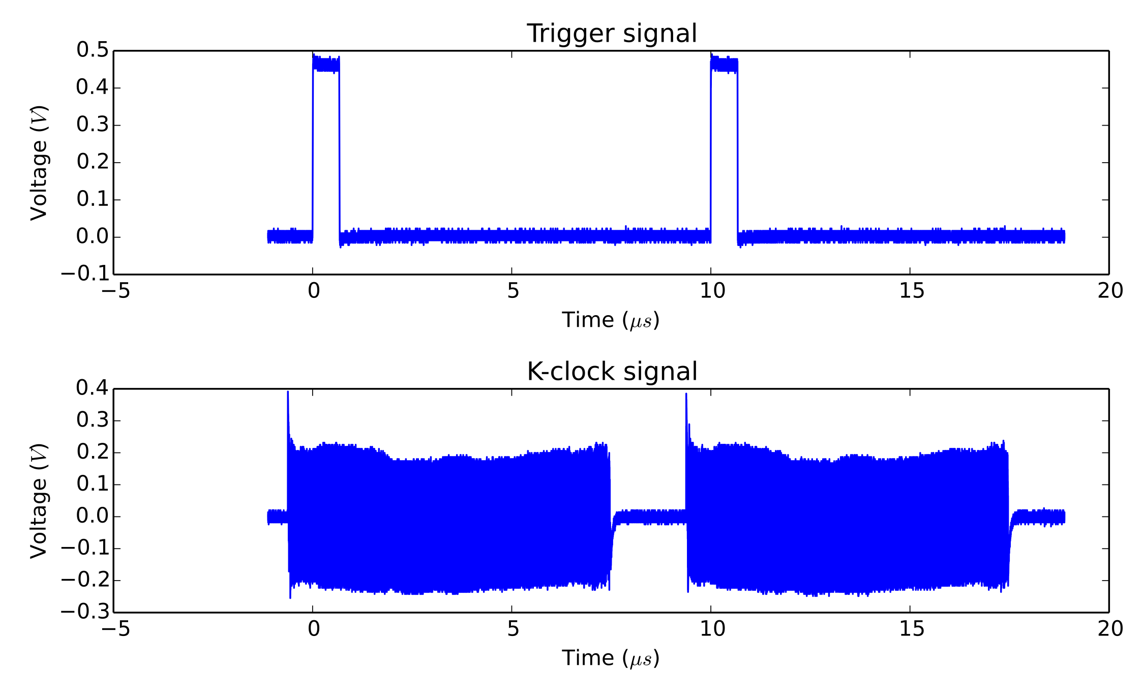
External clock issues can be of two natures; trigger jumps, or unexpected (glitchy) acquired data. These issues can also arise as the result of a board misconfiguration (bad record length, bad trigger configuration…). Before proceeding with the external clock troubleshooting, you must ensure that the external clock is indeed the cause of your problems. One way to do that is to make sure that your acquisition works fine when using the internal clock. Another way is to reproduce your acquisition configuration in AlazarDSO, and make sure that the problem also shows up there. Once having made sure that the external clock is the issue, the next step is to identify the problematic regions of the signal. To do this, please acquire a few record acquisition cycles (laser sweeps) with a high speed oscilloscope (ideally 20GS/s, 4GHz), and to send the results to us.
External Clock Measurement#
Here is an example of an external clock analysis plot, annotated to show the problem:
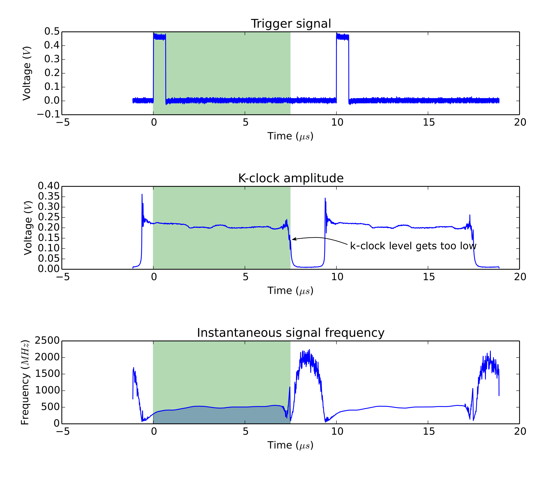
Example of external clock analysis#
Using AlazarOCTIgnoreBadClock() to solve external clock issues#
Some AlazarTech digitizers support a feature called OCT Ignore Bad Clock, which can be used to make the board ignore the external clock signal for a given period of time. This can be used if the external clock signal is bad when the board is not acquiring data. Note that the external clock signal must be good when trigger events are received, and when the board needs to acquire data.
In order to activate OCT Ignore Bad Clock, customers must first measure how long the external clock signal is good 1 after the trigger event, and how long it is bad. For example, the data of the Example of external clock analysis figure shows that the clock signal stays good for ~7.5µs, then goes bad for ~2µs.
The values of “good clock duration” and “bad clock duration” must add up to less than the trigger period, to ensure that the board is back to accepting the external clock before each trigger event. As an example, the data of the Example of external clock analysis shows that the trigger period is 10µs. This is compatible with choosing values of 7.5µs and 2µs for good and bad clock durations respectively.
Once these values are known, the only change that is required to add OCT Ignore
Bad Clock to an existing application is to call
AlazarOCTIgnoreBadClock() in the board configuration section of the
application.
- 1
The external clock signal is considered good when it meets the digitizer’s specified limits in terms of amplitude and frequency. The limits can be found on the digitizer’s datasheet.