Advanced Topics
External clock issues for OCT applications
The external clocking feature of AlazarTech boards is commonly used in OCT applications, where swept laser sources generate a signal to be used for clocking the acquisition. However, in some cases the external clock signal does not meet the requirements of the digitizers, which can lead to various issues. This section discusses the steps that need to be taken to diagnose and troubleshoot external clock problems.
Diagnose external clock issues
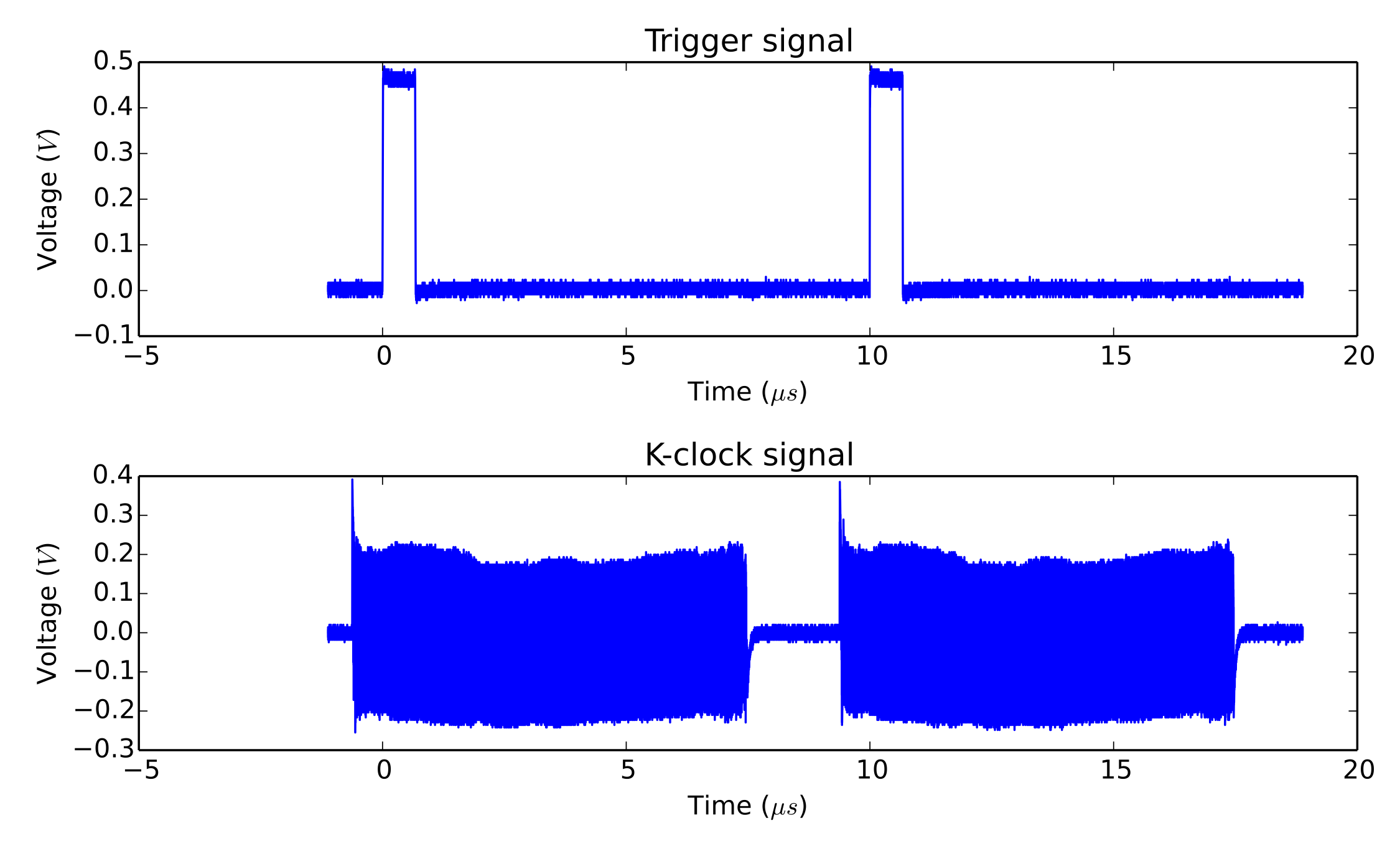
External clock issues can be of two natures; trigger jumps, or unexpected (glitchy) acquired data. These issues can also arise as the result of a board misconfiguration (bad record length, bad trigger configuration…). Before proceeding with the external clock troubleshooting, you must ensure that the external clock is indeed the cause of your problems. One way to do that is to make sure that your acquisition works fine when using the internal clock. Another way is to reproduce your acquisition configuration in AlazarDSO, and make sure that the problem also shows up there. Once having made sure that the external clock is the issue, the next step is to identify the problematic regions of the signal. To do this, please acquire a few record acquisition cycles (laser sweeps) with a high speed oscilloscope (ideally 20GS/s, 4GHz), and to send the results to us.

External Clock Measurement
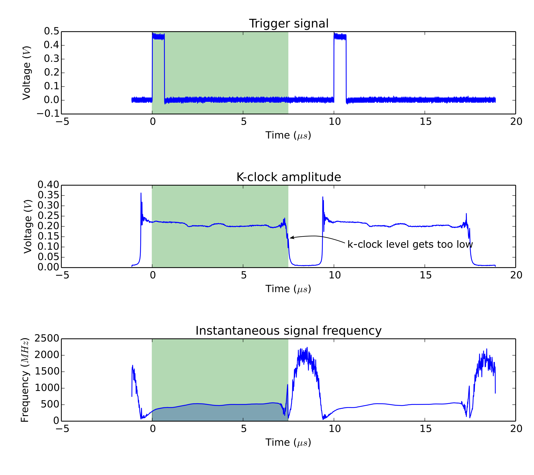
Here is an example of an external clock analysis plot, annotated to show the problem:

Example of external clock analysis
K-clock deglitching firmware
The k-clock deglitching firmware available for ATS9350 and ATS9351 is specifically designed to overcome k-clock related issues. If you are using one of these boards, trying this firmware is the next logical step. In our experience, it solves all k-clock related issues. ATS9360, ATS9370, ATS9371 and ATS9373’s firmwares include the deglitching feature by default.
AlazarSetTriggerOperationForScanning
AlazarTech digitizers require that the ADC clock be valid when an application
calls AlazarStartCapture() to arm a board to begin an acquisition. The
digitizer may not be able to start an acquisition if the the application calls
AlazarStartCapture() while the ADC clock is invalid. If an application
uses both external clock and external trigger signals, and the external clock is
not suitable to drive the ADC’s during part of the interval between trigger
events, the application can call
AlazarSetTriggerOperationForScanning() (rather than
AlazarSetTriggerOperation()) to configure the trigger engines. This
function configures the trigger engines to use an external trigger source
connected to the TRIG IN connector, and also allows the board to begin an
acquisition on the next external trigger event after the call to
AlazarStartCapture(), when the external clock signal is valid.
For example, some OCT applications use a laser source that supplies an external
clock signal that is valid on the rising edge of the trigger pulse, but falls to
0 Hz on the falling edge of the trigger pulse. The digitizer may not work
correctly if the application calls AlazarStartCapture() to arm the
board while the clock output is at 0 Hz. These applications can call
AlazarSetTriggerOperationForScanning() to configure the trigger
engines to use an external trigger input, and to wait until the first rising
edge of the external trigger pulse arrives after the call the
AlazarStartCapture() to start the acquisition, when the external clock
is valid:
RETURN_CODE
AlazarSetTriggerOperationForScanning (
  HANDLE handle,
  U32 SlopeId, // trigger slope identifier
  U32 Level, // trigger level code
  U32 Options // scanning options
  );
AlazarSetTriggerOperationForScanning() configures a board to use
trigger operation TRIG_ENGINE_OP_J, and configures the source of
TRIG_ENGINE_J to be TRIG_EXTERNAL. The application must
call AlazarSetExternalTrigger() to set the full-scale external input
range and coupling of the external trigger signal connected to the TRIG IN
connector. The slope identifier parameter selects if a trigger event should be
generated when the external trigger level rise above, or falls below, a
specified level. The parameter may have one of the following values.
TRIGGER_SLOPE_POSITIVE- The external trigger level rises above a specified level.
TRIGGER_SLOPE_NEGATIVE- The external trigger level falls below a specified level.
The trigger level parameter sets the external trigger level as an unsigned 8-bit code that represents a fraction of the external trigger full scale input range: 0 represents the negative full-scale input, 128 represents a 0 volt input, and 255 represents the positive full-scale input. In general, the trigger level value is given by:
TriggerLevelCode = 128 + 127 * TriggerLevelVolts / InputRangeVolts
The following table gives examples of how trigger level codes map to trigger levels in volts according to the external trigger full-scale input range.
| Trigger level code | Input fraction | Level with ±1V trigger range | Level with ±5V trigger range |
|---|---|---|---|
| 0 | -100% | -1V | -5V |
| 64 | -50% | -500 mV | -2.5 V |
| 96 | -25% | -250 mV | -1.25 V |
| 128 | 0% | 0 V | 0 V |
| 160 | +25 % | 250 mV | 1.25 V |
| 192 | +50% | +500 mV | +2.5 V |
| 255 | +100% | +1V | +5V |
The options parameter may be one of the following flags:
STOS_OPTION_DEFER_START_CAPTURE- Wait until the next external trigger event after the application calls
AlazarStartCapture()before arming the board to start the acquisition. The external clock input should be valid when the trigger event arrives.